Acer File Extensions |
Acer 3200 Motherboard
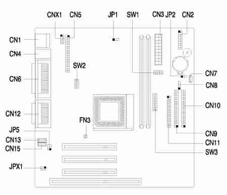
Jumper and Connector Layout
Jumper Settings
| Jumper | Setting | Function |
|---|---|---|
| JP1 - VGA Interrupt | 1-2 * 2-3 | Disabled Enabled |
| JP2 - Wake-On-LAN Setting | 1-2 2-3 * | Active Low Active High |
| JP5 & JPX1 - Audio Line Type | 1-3 & 2-4* 3-5 & 4-6 | Line Out Speaker Out |
| SW1-1 | Reserved | |
| SW2-1 | Reserved | |
| SW2-2 - Password Function | On Off* | Check Bypass |
| SW2-3, SW2-4 - Bus frequency (MHz) | Off, Off Off, On On, On* | 66 95 for AMD & 90 for Cyrix 100 |
| SW1 (switch 2, 3, 4) - Bus frequency (MHz) | |||||
|---|---|---|---|---|---|
| 2 | 3 | 4 | Host | AGP | PCI |
| Off | On | On | 66 | 66 | 33 |
| On | Off | Off | 95 | 66 | 33 |
| Off | Off | Off* | 100* | 66 | 33 |
| SW3 (switch 1, 2, 3) - CPU core clock multiplier | |||||
| 1 | 2 | 3 | P55C | M2 | K6 |
| Off | Off | Off* | 3.5 | 3.5 | 3.5 |
| On | Off | On | 2.0 | 2.0 | 4.0 |
| Off | On | Off | 3.0 | 3.0 | 3.0 |
| On | On | Off | 2.5 | 2.5 | 2.5 |
| On | On | On | --- | --- | 4.5 |
| On | Off | Off | --- | --- | 2.0 |
| Off | On | On | --- | --- | 5.0 |
| Off | Off | On | --- | --- | 5.5 |
| SW3 (switch 4, 5, 6, 7, 8) - CPU Core Voltage | |||||
| 4 | 5 | 6 | 7 | 8 | CPU Core Voltage |
| Off | On | On | Off | On | 3.3V |
| Off | On | On | Off | Off | 3.2V |
| Off | On | Off | Off | On | 2.9V |
| Off | On | Off | Off | Off | 2.8V |
| Off | Off | Off | On | On | 2.3V |
| Off | Off | Off | On | Off* | 2.2V |
Connector Functions
| Connector | Function |
|---|---|
| CN1 | Universal Serial Bus (USB) connector |
| CN2 | Power LED (pins 1-2) HDD LED (pins 4-7) Reset button (pins 8-9) Power button (pins 10, 20) IrDA connector (pins 14-19) Turbo LED (pins 11-13) |
| CN3 | Power connector |
| CN4 | Upper: PS/2 mouse port Lower: PS/2 keyboard port |
| CN5 | ATI multimedia connector |
| CN6 | Upper: Printer port Lower-left: VGA port Lower-right: Serial port |
| CN7 | Wake-On-LAN connector |
| CN8 | Modem ring-in connector |
| CN9 | Secondary IDE channel |
| CN10 | Primary IDE channel |
| CN11 | Diskette driver connector |
| CN12 | Upper: game/MIDI port (15-pin female) Lower: (R-to-L) - Microphone-in port, Stereo line-in port, Stereo line-out port |
| CN13 | Modem voice line-in connector |
| CN15 | CD/DVD audio input connector |
| CNX1 | USB Hub connector |
| FN3 | Fan connector |
Memory Upgrade
The system memory is upgradable to a maximum of 256 MB via two 168-pin DIMM sockets on board. These DIMM sockets accept 3.3 Volt PC-66/PC-100 compliant SDRAM DIMMs with 8, 16, 32, 64, and 128MB capacities.
Important! Do not use both PC-100 (100 MHz) and PC-133 (133 MHz) SDRAM together. Such a combination might cause your system to malfunction.
BIOS
How do I enter the BIOS Setup Utility?
You can access the BIOS Setup Utility by pressing CTRL+ALT+ESC as the system is booting. At the bottom of the second start up screen you should see "To enter setup, press CTRL_ALT_ESC".
Note: If the system displays the Acer Splash Screen, once you hear the beep, you should begin pressing CTRL+ALT+ESC. You may need to press CTRL+ALT+ESC continuously until you access the BIOS setup screen.
How do I disable the onboard sound?
To disable the onboard sound for this system, please follow the steps below:
- Press Ctrl+Alt+Esc to enter BIOS Setup Utility during system boot and before the operating system starts.
- Press ALT+F4 when the Setup Utility menus appears.
- Select Onboard Peripherals.
- Select Onboard Device Settings and change Onboard Audio Chip to Disabled
- Press Esc three times and choose yes to save CMOS changes.