 Acer File Extensions |
Acer A1G Motherboard
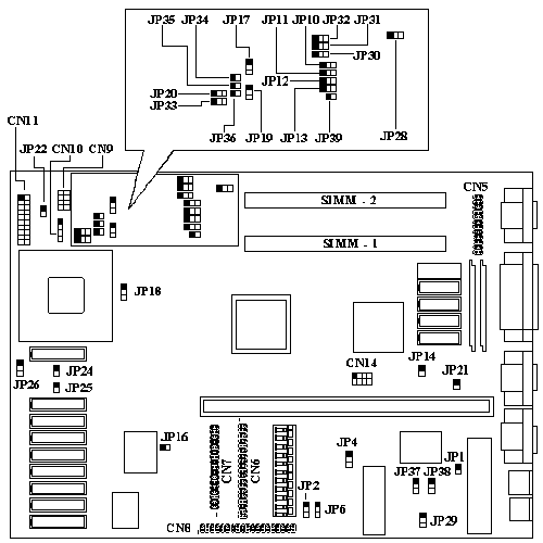
Jumper and Connector Layout

Note - The blackened pin of a jumper represents pin 1.
Overview
- Supports Full 486 Series CPU And Overdrive Processors
- Intel SL Enhanced CPU Smm/Smi Supported
- Microsoft/Intel Apm Compliant Bios
- Vesa Dpms Supported
- 4-Mb Memory Upgradable To 36-Mb
- Up To 256kb Write-Back Second-Level Cache
- Local-Bus Windows Accelerator
- Display Memory Upgradable To 2-Mb For GD-5428
- Maximum Resolution Up To 1280 By 1024 By 256 Colors
- 24-Bit True Color Display Modes Supported
- Programmable Hardware Cursor Up To 64 X 64 Pixels
- Optional Enhanced Ide Supports Up To 4 Devices, Including Cd-Rom And Tape Drive.
- Optional User-Upgradeable Flash Bios
- Multiple Security Levels
- Power Saving Modes
- Hdd Power Saving Mode
- Vga Monitor Power Saving Mode
- Stanby Mode
- Optional 0 Watt Suspend Mode
- Mechanical - Front Panel Suspend/Resume Button Security Features
Jumper Settings
| Jumper | Setting | Function |
|---|---|---|
| JP1 | OPEN | ACER BIOS |
| CLOSED | OEM BIOS | |
| JP2 | 1-2 | Enable Security |
| 2-3 | Disable Security | |
| JP4 | 1-2 | Flash ROM |
| 2-3 | EPROM | |
| JP14 | CLOSE | Enable On-Board VGA |
| OPEN | Disable On-Board VGA | |
| JP20 | 1-2 | S-Series CPU |
| 2-3 | Normal Intel or AMD | |
| JP21 | CLOSED | Enable M5105 |
| OPEN | Disable M5105 | |
| JP22 | OPEN | Lock Key |
| CLOSED | Unlock key | |
| JP28 | 1-2 | Enable On-Board Memory |
| 2-3 | Disable On-Board Memory or No On-Board Memory | |
| JP29 | 1-2 | CHRDY |
| 2-3 | POE (not in use) |
System CPU Clock Selection
| CPU Clock | JP7* | JP8* | JP9* | JP10 | JP17 | JP19 |
|---|---|---|---|---|---|---|
| 25MHz (DX2/50) | 2-3 | 2-3 | 1-2 | 2-3 | 2-3 | 1-2 |
| 33MHz (DX2/66) | 1-2 | 2-3 | 1-2 | 2-3 | 2-3 | 2-3 |
| 40MHz | 1-2 | 1-2 | 2-3 | 1-2 | 1-2 | 2-3 |
| 50MHz | 2-3 | 2-3 | 1-2 | 1-2 | 1-2 | 1-2 |
*CN14
3-7 = 33MHZ (DX2/66)
4-8 = 25MHZ (DX2/50)
* CPU clock selection will either be through JP7,JP8,JP9 or CN14.
CPU Type Selection
| CPU Type | JP11 | JP12 | JP13 | JP39 | JP18 | JP33 | JP30-32 | JP34-36 |
|---|---|---|---|---|---|---|---|---|
| 486 | 1-2 | 1-2 | 2-3 | CLOSED | 2-3 | 1-2 | OPEN | CLOSED |
Memory
The system board has two SIMM sockets that accept 4-MB, 8-MB, or 16-MB SIMMs, upto a maximum of 32MB (or 36MB if motherboard has 4MB on-board). 72 Pin, 70ns, Parity, Fast Page Mode SIMMS with gold tips recommended.
Cache RAM Upgrade Path
| Cache Size | SRAM Type | Location | JP24 | JP25 | JP26 |
|---|---|---|---|---|---|
| 64KB | 8K X 8 X 9 PCS | TAG, U56 TO U63 | OPEN | OPEN | 2-3 |
| 128KB | 32K X 8 X 5 PCS | TAG, U56,U58,U60,U62 | OPEN | CLOSED | 1-2 |
| 256KB | 32K X 8 X 9 PCS | TAG, U56 TO U63 | CLOSED | CLOSED | 2-3 |
Upgrade Video Memory
You can increase VGA RAM to 1 or 2 MB.
To upgrade the VGA RAM, do the following:
1. To upgrade from 512 to 1MB, order p/n 91.00023.901 from Acer Access. To upgrade from 1MB to 2MB order p/n 02.54260.030.
2. Locate the VGA memory expansion sockets on the system board labelled U12, U13, U15 and U16.
3. Gently but firmly insert a 44256 DRAM (256 K bit by 4, 70-ns) chip into each of the VGA memory expansion sockets.
Increasing VGA memory up to 2 MB is an option available to you. To do this, insert two 51460 (256 K bit by 16) DRAM chips on the sockets labelled U10 and U9.