Acer File Extensions |
Acer V12LC-2X Motherboard
Jumper and Connector Layout
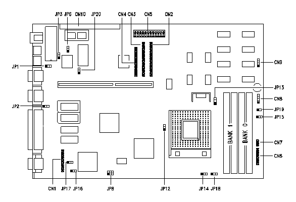
Note - The blackened pin of a jumper represents pin 1.
CPU configurations
| JCPU Speed | JP8 | JP14 | JP18 |
|---|---|---|---|
| P75 | 1-4 | 1-2 | 1-2 |
| P90 | 2-5 | 1-2 | 1-2 |
| P100 | 3-6 | 1-2 | 1-2 |
| P120 | 2-5 | 2-3 | 1-2 |
| P133 | 3-6 | 2-3 | 1-2 |
| P150* | 2-5 | 2-3 | 2-3 |
| P166 | 3-6 | 2-3 | 2-3 |
*BIOS version R04-E7 is required for 150MHz Pentium operation for systems with the Cirrus Logic GD5440 chipset. BIOS version R04-E8 is required for 150MHz Pentium operation for systems with the Cirrus Logic GD5434 chipset.
Jumper Settings
| Jumper | Setting | Function | |||||||||||||||
|---|---|---|---|---|---|---|---|---|---|---|---|---|---|---|---|---|---|
| JP1 | 1-2* 2-3 | For models with Acer BIOS For models with OEM BIOS | |||||||||||||||
| JP2 Password | 1-2 2-3* | Check password Bypass password | |||||||||||||||
| JP3 BIOS ROM | Open 1-2 2-3* | SST29EE010 BIOS ROM only EPROM BIOS ROM Flash ROM (Intel 28F010, 28F001, 28F101) | |||||||||||||||
| JP6 Onboard I/O | 1-2 2-3* | Disable onboard SMC665/669 Enable onboard SMC665/669 | |||||||||||||||
| JP8 CPU clock frequency | 1-4 2-5* 3-6 | 50 MHz clock freq (Pentium 75 MHz) 60 MHz clock freq (Pentium 90/120/150 MHz) 66 MHz (Pentium 100/133 MHz) | |||||||||||||||
| JP12 CPU Type | 1-2* 2-3 | Intel P54C or AMD K5 CPU Cyrix M1 CPU | |||||||||||||||
| JP13 CPU Voltage | 1-2* 2-3 | 3.3825V for VR and standard CPU type 3.5250V for VRE CPU type | |||||||||||||||
| JP14, JP18 CPU Clock Ratio |
|
| |||||||||||||||
| JP15 Reset Switch | 1-2 2-3* | For suspend mode function For reset function | |||||||||||||||
| JP16, JP17 CN1 Function | 1-2* 2-3 | Feature connector I2C interface | |||||||||||||||
| JP19 HD LED | Open* | LED flashes whenever it detects disk activity Note: Keep JP19 open. | |||||||||||||||
| JP20 Intel 28F001 | 1-2 2-3* | Programming boot block (for AFlash util use) Normal (programming all other blocks) |
Connector Functions
| Connector | Function |
|---|---|
| CN1 | VGA feature connector |
| CN2 | PCI IDE channel 1 |
| CN3 | PCI IDE channel 2 |
| CN4 | Diskette drive connector |
| CN5 | Power connector |
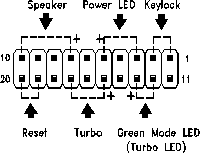
| CN6 | Multifunction connector |
| CN7 | Multifunction connector |
| CN8 | Hard disk LED connector |
| CN9 | Reserved |
| CN10 | Feature socket for multimedia or Ethernet card |
| Multifunction connector CN6 This connector accommodates the front panel connectors for speaker, LEDs, keylock, reset, and turbo. Figure 1-3 shows the CN6 pin assignments for each of the front panel connectors. |
 |
Cache
The V12LC-II ships with 0KB or 256KB 2nd Level Cache, and is not upgradeable.
Memory
Memory type : 72-Pin, 70ns, Non-Parity Fast Page Mode SIMMS with gold tips. Maximum : 128MB
Video Memory
Larger video memory allows you to display more colors* at higher resolutions. The system board comes with 1-MB video memory onboard upgradable to 2 MB. Order the video upgrade kit from Acer Access P/N 91.AA319.001.
*800x600x16 million colors is not available when video memory is upgraded to 2 MB on CL-5430 and CL-5440 chipsets.