Acer File Extensions |
Acer V35 Motherboard
Jumper and Connector Layout
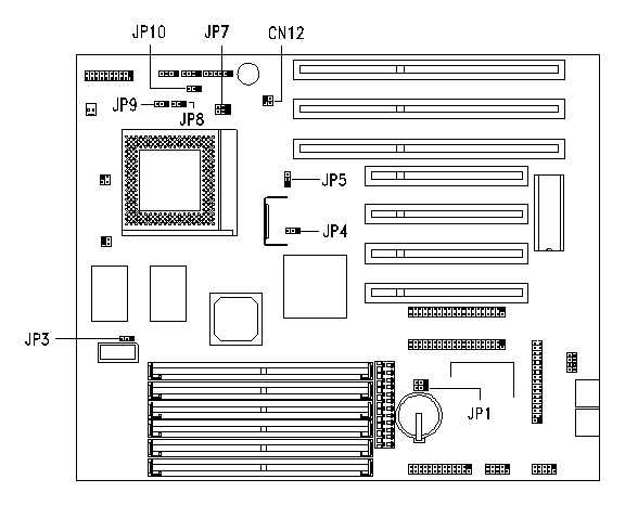
Note - The blackened pin of a jumper represents pin 1.
System Information
- CPU Information:
- Socket - ZIF Socket 7
- CPU Types -
- Intel Pentium 75
- Intel Pentium 90
- Intel Pentium 100
- Intel Pentium 120
- Intel Pentium 133
- Intel Pentium 150
- Intel Pentium 166
- Clockspeeds
- 50 MHz (Pentium 75 MHz)
- 60 MHz (Pentium 90/120/150 MHz)
- 66 MHz (Pentium 100/133/166 MHz)
- On-Board Memory:
- 0 MB RAM
- 256 KB Pipe-Lined Burst Cache (cache not upgradeable)
- BIOS Type: Flash
- Bus Type:
- 3 ISA
- 4 PCI (PCI BUS 2.1 Compliant)
- (one PCI/ISA shared)
- On-Board Controller: SMC
- Chipset: Intel 82439HX (Triton II)
- I/O Ports: 2 9-pin Serial NS16C550 Compatible, 1 25-pin Parallel (ECP/EPP)
- IDE Interface: 2 IDE ports for a maximum of 4 IDE Devices fully compatible with ANSI ATA Rev 3.0 and ATAPI specifications
- Case: IDABN
Memory Upgrade
- SIMM Sockets : (6) 72-pin Sockets - 3 Banks
- Maximum RAM : 192 MB
- SIMM Type : 4/8/16/32MB 72-pin parity/nonparity 60ns Standard Page Mode/EDO.
CPU Jumper settings
| CPU Freq, | JP4 | JP8 | JP9 | CN12 |
|---|---|---|---|---|
| 75 MHz | 1-2 | 1-2 | 1-2 | 1-3, 2-4 |
| 90 MHz | 2-3 | 1-2 | 1-2 | 2-4 |
| 100 MHz | 2-3 | 1-2 | 1-2 | 1-3 |
| 120 MHz | 2-3 | 2-3 | 1-2 | 2-4 |
| 133 MHz | 2-3 | 2-3 | 1-2 | 1-3 |
| 150 MHz | 2-3 | 2-3 | 2-3 | 2-4 |
| 166 MHz | 2-3 | 2-3 | 2-3 | 1-3 |
| 200MHz** | 2-3 | 1-2 | 2-3 | 1-3 |
**BIOS revisions below Service BIOS v2.0R01-D4 will display the 200MHz CPU setting as 166MHz--the actual system speed is 200MHz.
Jumper Settings
| Jumper | Setting | Function |
|---|---|---|
| JP1 | 1-2 2-3* | Check password Bypass password |
| JP3 | 1-2 * 2-3 | 64-MB cacheable memory Reserved |
| JP5 | 1-2 2-3* | 3.3V operating voltage 3.6V operating voltage |
| JP7 | 1-2 2-3* | Disables second-level cache Enables 256-KB L2 cache size |
| JP10 | 1-2 2-3* | Enables SMI switch Enables Reset switch |
Connector Functions
| Connector | Function |
|---|---|
| CN1 | Serial port 1 |
| CN2 | Serial port 2 |
| CN3 | Parallel port |
| CN4 | Power connector |
| CN5 | Diskette drive connector |
| CN7 | USB connector |
| CN8 | IDE connector 1 |
| CN9 | IDE connector 2 |
| CN13 | IR connector |
| CN15 | Disk drive LED connector |
| CN16 | Multifunction connector |
| C01 | Two-pin fan connector |
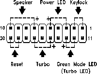
| The multifunction connector CN16 accommodates the front panel connectors for speaker, LEDs, keylock, reset, and turbo. Figure below shows the pin assignments for each connector. |
 |