 Acer File Extensions |
Acer V58XA Motherboard
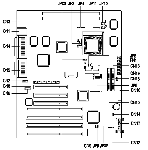
Jumper and Connector Layout

Note - The blackened pin of a jumper represents pin 1.
CPU Jumper Settings
| Processor | JP3 | JPX3 | JP4 | JP5 | JP6 | JP10 | JP11 |
|---|---|---|---|---|---|---|---|
| Pentium P-166 | Open | 2-3 | 2-3, 5-6 | Clsd | 1-3 | 3-4, 5-6 | 1-3, 2-4 |
| Pentium P-200 | Open | 2-3 | 2-3, 4-5 | Clsd | 1-3 | 3-4, 5-6 | 1-3, 2-4 |
| Pentium 166 MMX | Clsd | 2-3 | 2-3, 5-6 | Open | 2-4 | 3-5, 4-6 | 1-3, 2-4 |
| Pentium 200 MMX | Clsd | 2-3 | 2-3, 4-5 | Open | 2-4 | 3-5, 4-6 | 1-3, 2-4 |
| Pentium 233 MMX | Clsd | 2-3 | 1-2, 4-5 | Open | 2-4 | 3-5, 4-6 | 1-3, 2-4 |
| Cyrix 6x86L PR166+ | Clsd | 2-3 | 1-2, 5-6 | Open | 2-4 | 3-5, 4-6 | 1-3, 2-4 |
| Cyrix 6x86L PR200+ | Clsd | 2-3 | 1-2, 5-6 | Open | 2-4 | 1-3, 2-4 | 3-5, 4-6 |
| Cyrix 6x86MX PR166+ | Clsd | 2-3 | 1-2, 5-6 | Open | 4-6 | 3-5, 4-6 | 1-3, 2-4 |
| AMD K6 PR166 | Clsd | 2-3 | 2-3, 5-6 | Open | 4-6 | 3-5, 4-6 | 1-3, 2-4 |
| AMD K6 PR200 | Clsd | 2-3 | 2-3, 4-5 | Open | 4-6 | 3-5, 4-6 | 1-3, 2-4 |
| AMD K6 PR233 | Clsd | 2-3 | 1-2, 4-5 | Open | 7-8 | 3-5, 4-6 | 1-3, 2-4 |
| for PCB number: 97114-2: | |||||||
| AMD K6 PR266 | Clsd | 1-2 | 1-2, 5-6 | Open | 3-5 | 3-5, 4-6 | 1-3, 2-4 |
| AMD K6 PR300 | Clsd | 1-2 | 2-3, 5-6 | Open | 3-5 | 3-5, 4-6 | 1-3, 2-4 |
Jumper Settings
| Jumper | Setting | Function |
|---|---|---|
| JPX2 - BIOS Logo Setting | 1-2 | Acer BIOS |
| 2-3 | OEM BIOS | |
| JP9 - Password Security | 1-2 | Check Password |
| 2-3 | Bypass Password |
Connector Functions
| Connector | Function |
|---|---|
| CN1 (lower) | PS/2 Connector - Keyboard |
| CN1 (upper) | PS/2 Connector - Mouse |
| CN2 | Modem/Voice-in Connector |
| CN3 | Universal Serial Bus (USB) |
| CN4 | Video Out |
| CN4 (upper) | Printer Port |
| CN4 (lower) | Serial Port |
| CN5 (upper) | MIDI/Game Port |
| CN5 (lower) | Line Out/Line In/ Mic. |
| CN6 | CD Audio Connector |
| CN8 | ATI Media Connector (AMC) |
| CN9 | Modem ring-in / wake up |
| CN10 | Secondary IDE Channel |
| CN12 | Hard Disk Drive LED |
| CN13 | Primary IDE Channel |
| CN14 | Power/Suspend Switch Conn. |
| CN15 | Standby Power Connector |
| CN16 | Floppy Diskette Connector |
| CN17 | Power LED Connector |
| CN19 | System Board Power Connector |
| FN1 | Processor Fan Connector |
Memory
The system memory is upgradable to a maximum of 256MB via two DIMM sockets on board. These DIMM sockets accept 32MB, 3.3V or 5V DRAM modules in capacities of 8-, 16-, 32, 64 and 128MB. It supports ECC and Parity features for DRAM. This motherboard accepts Fast Page Mode, EDO, and SDRAM DIMMs.
Cache
The Cache Memory for the V58XA Motherboard is 256k or 512k (dependant on the system model) is soldered on and not upgradeable.
Enabling USB
To enable the USB ports follow these steps:
- To access the CMOS Setup Utility
Press [Ctrl] + [Alt] + [Esc] early in the boot-up process, after the first beep but before the operating system loads. It may be necessary to hold down the [Ctrl] + [Alt] keys while repeatedly tapping the [Esc] key in order to get the timing right.
- Select Onboard Peripheral Configuration
- Page down to Page 2
- Change USB Host Controller to [Enabled]
- Save and Exit the Setup Utility
How do I access my BIOS?
Resolution: You can access the BIOS by pressing CTRL+ALT+ESC as the system is booting. At the bottom of the second start up screen you should see "To enter setup, press CTRL_ALT_ESC".
Note: If the system displays the Acer Splash Screen, once you hear the beep, you should begin pressing CTRL+ALT+ESC. You may need to press CTRL+ALT+ESC continuously until you access the BIOS setup screen.