Acer File Extensions |
Acer V70MA Motherboard
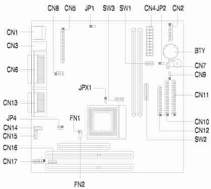
Jumper and Connector Layout
Jumper and Switch settings
| Switch / Jumper | Setting | Function |
|---|---|---|
| JP1 | 1-2* 2-3 | VGA Interrupt Enabled VGA Interrupt Disabled |
| JP2 | 1-2 2-3* | Wake-on LAN Active low Wake-on LAN Active high |
| JP4 | 1-2, 4-5 2-3, 5-6* | Audio Line-in Source - AMC connector Audio Line-in Source - Line-in connector |
| JPX1 | 1-2 2-3* | CPU Type - AMD K6S-300 CPU Type - Other CPUs |
| SW3-B1 | On* OFF | AMD K65-300 Voltage Select 3.45 V AMD K65-300 Voltage Select - 3.60 V |
| SW3-B2 | On OFF* | Check password Bypass password |
| SW3-B3, SW3-B4 | Off, Off On, Off On, Off On*, On* | M1542 Bus Frequency - 66 M1542 Bus Frequency - 75 M1542 Bus Frequency - 95 M1542 Bus Frequency - 100 |
| SW2 Settings | ||||
|---|---|---|---|---|
| CPU Core Clock Multiplier | ||||
| B1 | B2 | B3 | K6 | |
| Off | Off | Off | 3.5 | |
| On | Off | On | 4.0 | |
| Off* | On* | Off* | 3.0* | |
| On | On | Off | 2.5 | |
| On | On | On | 4.5 | |
| On | Off | Off | 2.0 | |
| Off | On | On | 5.0 | |
| Off | Off | On | 5.5 | |
| SW2 Settings | |||||
|---|---|---|---|---|---|
| CPU Core Voltage | |||||
| B4 | B5 | B6 | B7 | B8 | Voltage |
| Off | On | On | Off | On | 3.3 |
| Off | On | On | Off | Off | 3.2 |
| Off | On | Off | Off | On | 2.9 |
| Off | On | Off | Off | Off | 2.8 |
| Off | Off | Off | On | On | 2.3 |
| Off* | Off* | Off* | On* | Off* | 2.2* |
Connector Functions
| Connector | Function |
|---|---|
| CN1 | USB port |
| CN2 | Power LED (pins 1-3) HDD LED (pins 4-7) Reset button (pins 8-9) Power button (pins 10, 20) IrDA connector (pins 14-19) Turbo LED (pins 11-13) |
| CN3 | Upper: PS/2 mouse port Lower: PS/2 keyboard port |
| CN4 | ATX power connector |
| CN5 | ATI AMC feature connector |
| CN6 | Upper: Parallel port Lower: VGA port (right), COM2 port (left) |
| CN7 | Wake-on LAN connector |
| CN8 | COM1 port |
| CN9 | Modem ring-in connector |
| CN10 | IDE2 connector |
| CN11 | IDE1 connector |
| CN12 | Floppy disk drive connector |
| CN13 | Upper: Game/MIDI port Lower: (R-to-L) - Microphone-in port, Stereo line-in port, Stereo line-out port |
| CN14 | Fax/voice connector |
| CN15 | CD-in connector |
| CN16 | Volume control connector |
| CN17 | External CS4610 connector |
| FN1 | 2-pin CPU fan connector |
| FN2 | 5-pin CPU fan connector |
Memory
The system memory is upgradable to a maximum of 256MB via two 168-pin DIMM sockets on board. These DIMM sockets accept 8-, 16-, 32-, 64-, and 128-MB standard DRAMs with Parity Check or Error Correction Code (ECC) feature at the 66MHz bus speed and 16-, 32-, 64-, and 128-MB PC100 SDRAM at the 100MHz bus speed. The additional RAM should be 168-pin, 10ns, and 3.3V DIMMs. Use normal SDRAMs (PC-66) for 333MHz CPU´s and below, while using PC100 SDRAMs for 350MHz CPU´s and above. When installing DIMMS, ensure that you install only one type of DIMM. Do not combine PC-66 and PC-100 DIMMs.
Enabling USB
To enable the USB ports follow these steps:
- To access the CMOS Setup Utility
Press [Ctrl] + [Alt] + [Esc] early in the boot-up process, after the first beep but before the operating system loads. It may be necessary to hold down the [Ctrl] + [Alt] keys while repeatedly tapping the [Esc] key in order to get the timing right.
- Select Onboard Peripheral Configuration
- Page down to Page 2
- Change USB Host Controller to [Enabled]
- Save and Exit the Setup Utility
How do I access my BIOS?
Resolution: You can access the BIOS by pressing CTRL+ALT+ESC as the system is booting. At the bottom of the second start up screen you should see "To enter setup, press CTRL_ALT_ESC".
Note: If the system displays the Acer Splash Screen, once you hear the beep, you should begin pressing CTRL+ALT+ESC. You may need to press CTRL+ALT+ESC continuously until you access the BIOS setup screen.
How do I disable the onboard video?
To disable the onboard video for this system, please follow the steps below:
- Press Ctrl+Alt+Esc to enter BIOS Setup Utility during system boot and before the operating system starts.
- Press Alt+F4 when the Setup Utility menus appears.
- Select Boot Options.
- Change Primary Display Driver to Auto
- Press Esc three times and choose yes to save CMOS changes.