Acer File Extensions |
Apricot Lightning Motherboard
Front View
Mini-tower
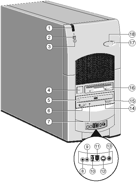 | |||
| 1. | Infra-red sensor | 10. | Universal Serial Bus (USB) port |
| 2. | Hard disk activity indicator | 11. | FireWire port (factory option) |
| 3. | Power Mode light | 12. | S-Video In port (factory option) |
| 4. | Power button | 13. | Composite Video In port (factory option) |
| 5. | CD-ROM disc drawer (platter) | 14. | CD emergency eject hole |
| 6. | CD headphone jack & volume control | 15. | CD Eject button |
| 7. | CD activity indicator | 16. | Diskette drive |
| 8. | Line In socket for audio input | 17. | Message LED alerts you that you have an unread message |
| 9. | Headphones socket | 18. | Message Cancel button clears the Message LED alert |
Desktop
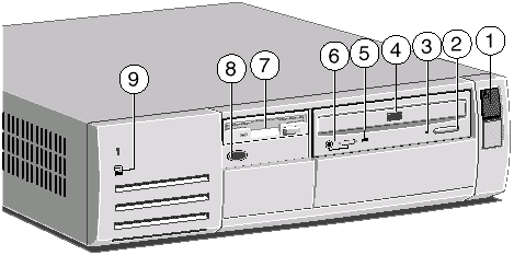 | |||
| 1. | Power button | 6. | CD phono jack & volume control |
| 2. | CD Eject button | 7. | Diskette drive |
| 3. | CD emergency eject hole | 8. | Infra-red sensor (optional) |
| 4. | CD-ROM disc drawer (platter) | 9. | Hard disk activity indicator |
| 5. | CD activity indicator | ||
Rear View
Mini-tower
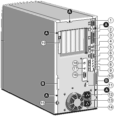 | |||
| 1. | Monitor port | 12 | AC power outlet for monitor |
| 2. | S-Video Out Port (factory option) | 13 | Voltage selection switch |
| 3. | Parallel (printer) port | 14. | AC power inlet from AC supply |
| 4. | Mouse port | 15. | Caselock |
| 5. | Keyboard port | 16. | MIDI/Joystick port |
| 6. | Serial port | 17. | Auxiliary Line In socket (factory option) |
| 7. | Microphone socket | 18. | SPDIF digital audio output (factory option) |
| 8. | Line Out socket for audio output | 19. | Modem port |
| 9. | Speaker socket | ||
| 10. | Universal Serial Bus (USB) port | A. | Side panel fixing screws |
| 11. | Security loop for cable or padlock | B. | Handles to assist side panel removal |
Desktop
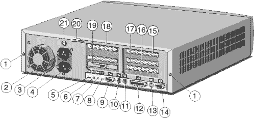 | |||
| 1. | Casing screws for the top cover | 12. | Parallel (printer) port |
| 2. | AC power outlet for monitor | 13. | Video out port (option) |
| 3. | Voltage selection switch | 14. | Monoitor port |
| 4. | AC power inlet from AC supply | 15. | PCI slot (full-length) |
| 5. | Double USB port | 16. | ISA slot (full-length) |
| 6. | Audio output (speaker) jack | 17. | ISA slot (half-length) |
| 7. | Audio line-out jack | 18. | PCI slots (two half-length) |
| 8. | Microphone input jack | 19. | Serial port 2 (optional) |
| 9. | Serial (modem) port 1 | 20. | Security loop for cable or padlock |
| 10. | PS/2 Keyboard port | 21. | Caselock (key supplied) |
| 11. | PS/2 Mouse port | ||
Motherboard
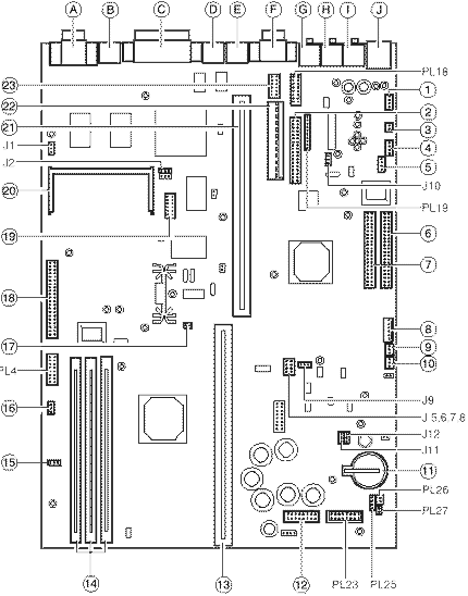 | |||
| 1 | Auxiliary Line In internal connector (option) | 12 | Front panel conn. option |
| 2 | 1.44MB diskette drive connector | 13 | Processor slot |
| 3 | S/P Dif. (option) dig. audio | 14 | DIMM sockets |
| 4 | CD audio connector | 15 | Case fan connector |
| 5 | Front panel USB internal connector (option) | 16 | CPU fan connector |
| 6 | Primary E-IDE connector | 17 | Processor heat sense input |
| 7 | Secondary E-IDE connector | 18 | VEC/AMC feature connector |
| 8 | PSU logic connector | 19 | TV tuner connector (option) |
| 9 | ‘Wake on LAN’ connector | 20 | Video memory upgrade socket |
| 10 | "Wake on Call" Modem connector | 21 | Riser board connect |
| 11 | CMOS battery | 22 | Motherboard power connector |
| 23 | COM2 interface (option) | ||
| J1 | On-board video enable/disable | A | Monitor port |
| J2 | BIOS program enable/disable | B | TV Out (S-Video) port (factory option) |
| J5-8 | Processor clock multipliers | C | Parallel (printer) port |
| J9 | DSP enable/disable (option) | D | PS/2 Mouse port |
| J10 | Audio subsystem enable/disable | E | PS/2 Keyboard port |
| J11 | Red power LED enable/disable | F | Serial port COM1 |
| J12 | Clear CMOS | G | Microphone socket |
| PL4 | Server management (option) | H | Line Out socket |
| PL18 | Joystick/MIDI internal connector | I | Speaker socket |
| PL19 | Voice modem audio connector | J | Dual USB port |
| PL23 | Front panel controls/options | ||
| PL25 | Internal case speaker (if fitted) | ||
| PL26 | Message light (option) | ||
| PL27 | Message switch (option) | ||
Note : Lightning incorporates Intel 440LX chipset (66MHz system bus)
Lightning BX incorporates Intel 440BX chipset (66 or 100MHz system bus)
Memory
The motherboard’s three DIMM sockets accept DIMMs of up to 128 Mbytes in any combination (giving a maximum memory capacity of 384 Mbytes). The slot 'MM1'nearest to the processor is recommended to be used first.
Note that the Lightning and Lightning BX motherboards use DIMMs of different specifications. See below for details and ensure that you fit the correct type.
Lightning - The DIMMs you use must have the following specification: gold contacts, 3.3V, 64 or 72-bit, unbuffered, SDRAM-type with Serial Presence Detect (SPD) and a CAS latency of 2 at 66 MHz. If you use any other type of DIMM you risk damaging the motherboard.
Lightning BX - The DIMMs you use must meet the following specification: Serial Presence Detect (SPD), gold contact, 64-bit, (or 72-bit ECC), unbuffered, 3.3V, SDRAM type, Intel PC100 spec compliant.
The ECC capabilities of 72-bit DIMMs will only operate if all the DIMMs in the system are 72-bit.
Using DIMMs of a different type could affect system performance with arisk of damaging the motherboard.
MS600 (MV) Processor Upgrades Page
This is the processor upgrade page for MS600 with the model number prefix MV.
To use the tables below, select the processor you wish to upgrade to and confirm that the upgrade is possible. Then check additional requirements such as BIOS upgrades & processor speed jumper settings.
| MS600 (MV) Processor upgrades | |
|---|---|
| Processor type and speed | Is it supported? |
| Pentium II 233Mhz | YES |
| Pentium II 266Mhz | YES |
| Pentium II 300Mhz | YES |
Listed below are the Processor Speed Jumpers for an MS Series computer with a model number prefix of MV.
| Processor Speed Jumper Table (I=jumper fitted, O=No jumper) | ||||
|---|---|---|---|---|
| J5 | J6 | J7 | J8 | CPU Speed |
| I | I | I | O | 200 |
| O | I | I | O | 233 |
| I | I | O | I | 266 |
| O | I | O | I | 300 |
BIOS Upgrade
For MV (MS600) model machines, there is no updated BIOS currently available.
Cache
Cannot be Upgraded
Video RAM
Cannot be Upgraded
Jumper Settings
There are only a few jumpers on the motherboard that you may need to alter. All others are set at the factory and should not be changed.
On the motherboard, pin 1 of each jumper block is indicated by a small triangular marking.
Warning - Do not change jumper settings unnecessarily as you may damage the system processor, the motherboard, or both.
On-board video disabling (J1)
If you install a video adapter expansion card, the computer should automatically detect this and disable the on-board video adapter. If for some reason this does not happen, and you experience problems with a newly-fitted card, you can manually disable the on-board video adapter by moving jumper J1 from position 2-3 (EN) to position 1-2 (DIS).
Processor multiplier (J5 to J8)
The details below are given for the clock speeds of processors known at the time of writing. Higher speed and overdrive processors may become available, in which case consult your supplier for further information.
In the case of the Lightning BX, the processor will send information to the BIOS and the BX chipset, ensuring that the required bus frequency is set automatically.
You then have to set the links as below.
| CPU bus speed | ||||||
|---|---|---|---|---|---|---|
| J5 | J6 | J7 | J8 | Ratio | 66MHz bus | 100MHz bus * |
| I | I | I | O | 3 | 200 | - |
| O | I | I | O | 3.5 | 233 | 350 |
| I | I | O | I | 4 | 266 | 400 |
| O | I | O | I | 4.5 | 300 | 450 |
| I | I | O | O | 5.0 | 333 | - |
I = jumper fitted, O = No jumper
* Lightning BX only
Audio DSP (J9)
If you need to disable the PCI audio accelerator (DSP) move jumper J9 from pins 1-2 (EN) to pins 2-3 (DIS).
Audio disabling (J10)
The on-board audio system can be disabled by removing jumper J10 from pins 1-2 (EN) to pins 2-3 (DIS). Disabling the audio system frees the interrupt and DMA channel used by that system (normally IRQ5 and DMA1).
BIOS upgrade and reprogram (J12, J2)
These jumpers should not normally be changed except by a service engineer or at the direction of a service engineer.
CMOS is cleared by moving the jumper J12 to the 2-3 (CLR) position for a few moments while the system is turned off and the power cord removed, then returning it to the 1-2 (NOR) position. It must be returned to normal before the power is reconnected.
BIOS reprogramming (J2) requires special software.
| J12 - Clearing CMOS | 1-2* | CMOS battery connected (default) |
| 2-3 | CMOS battery disconnected | |
| J2 - BIOS reprogramming | 1-2 | Enabled |
| 2-3 | Disabled |
* This jumper must be returned to the normal position before reconnecting the power cord.
Fan Connectors, PL3 & PL2
| Pins | CPU Fansink PL3 | Pins | Main fan PL2 |
|---|---|---|---|
| 1 | Ground | 1 | Ground |
| 2 | + 12v | 2 | + 12v (controlled)* |
| 3 | Fan Fail | 3 | Fan Fail |
* This voltage varies to control the fan speed. This is determined from the processor’s heatsink temperature sensor.
CMOS
Replacing the configuration battery
The computer keeps a record of its current hardware configuration in a CMOS memory chip which is sustained by a small battery. This battery has a life of up to 5 years. If you find that you have to reconfigure the computer every time you turn it on, the battery is probably failing and needs to be replaced.
The battery is a 3 volt lithium type (CR2032 or equivalent) typically used in calculators and other small, battery-powered electronic items.
To replace the battery
Turn off the computer and unplug all power cords.
Take suitable anti-static precautions and remove the right side panel.
Using a non-conductive implement, release the latch that holds the battery in place. The battery will pop up allowing you to lift it out of the holder.
Danger! You must not use a metal or other conductive implement to remove the battery. If a short-circuit is accidentally made between the battery’s positive and negative terminals, the battery may explode.
Check that the replacement battery looks the same as the battery you have removed.
Taking care not to touch the top or bottom surface of the battery, pick up the replacement with the positive (+) terminal upwards. Press the battery into the holder using a non-conductive implement.
Refit the right side panel.
Dispose of the discharged battery in accordance with the battery manufacturer’s instructions.
The next time you turn on the computer you will have to run the BIOS Setup utility to reset the hardware configuration.
System Resources
| Components | Interrupts (IRQs) | |||||||||||||||
|---|---|---|---|---|---|---|---|---|---|---|---|---|---|---|---|---|
| 0 | 1 | 2 | 3 | 4 | 5 | 6 | 7 | 8 | 9 | 10 | 11 | 12 | 13 | 14 | 15 | |
| System timer | ||||||||||||||||
| Keyboard controller | ||||||||||||||||
| PIC daisy chain | ||||||||||||||||
| Infra-red remote control BS | ||||||||||||||||
| Serial port 1 BS | ||||||||||||||||
| Audio JS | ||||||||||||||||
| Diskette controller BS | ||||||||||||||||
| Parallel port (usually sharable) | ||||||||||||||||
| Real time clock | ||||||||||||||||
| On-board video (sharable) JS | ||||||||||||||||
| USB (sharable) BS | ||||||||||||||||
| Mouse BS | ||||||||||||||||
| Co-processor | ||||||||||||||||
| Primary E-IDE BS | ||||||||||||||||
| Secondary E-IDE BS | ||||||||||||||||
| Components | DMA channels | |||||||
|---|---|---|---|---|---|---|---|---|
| 0 | 1 | 2 | 3 | 4 | 5 | 6 | 7 | |
| Audio JS | ||||||||
| Diskette controller BS | ||||||||
| Parallel port (in ECP mode) BS | ||||||||
| DMAC daisy chain | ||||||||
Key
| Fixed assignment | BS = Can be Disabled in Bios | |
| Usual assignment | JS = Can be disabled by motherbaord jumper | |
| Alternative assignment by BIOS Setup | ||
| Alternative assignment by Plug-and-Play |
POST Beep Codes
| Code | Beeps | Test which failed |
|---|---|---|
| 16 | 1-2-2-3 | BIOS ROM checksum |
| 20 | 1-3-1-1 | DRAM refresh. |
| 22 | 1-3-1-3 | 8742 keyboard controller |
| 2C xxxx | 1-3-4-1 | RAM failure on address line xxxx. |
| 2E xxxx | 1-3-4-3 | RAM failure on data bits xxxx of low byte of memory bus. |
| 30 xxxx | 1-4-1-1 | RAM failure on data bits xxxx of high byte of memory bus. |
| 46 | 2-1-2-3 | Check ROM copyright notice |
| 58 | 2-2-3-1 | Test for unexpected interrupts |
| 98 | 1-2 | Video configuration failure, or option ROM checksum failure. (One long, two short beeps.) |