Acer File Extensions |
Packard Bell 1030 M/Board
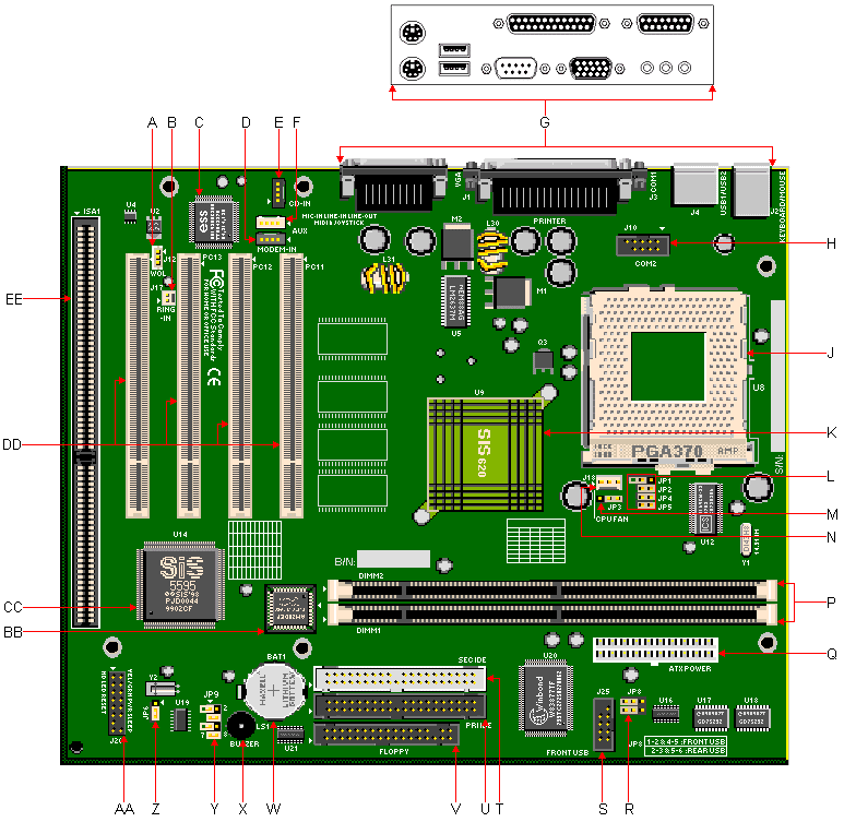
| Item | Description | Item | Description |
|---|---|---|---|
| A | Wake-On-LAN Header (J12) | R | USB Select Jumper Block (JP8) |
| B | Ring-In (Wake-On-Ring) Header (J17) | S | Front Side USB Connector |
| C | ESS 1938 Audio Controller | T | Secondary IDE Connector |
| D | Modem-In Header (J11) | U | Primary IDE Connector |
| E | CD-In Header (J5) | V | FDD Connector |
| F | Aux-In Header (J9) | W | Battery |
| G | Rear Ports | X | Piezo Buzzer |
| H | COM2 Connector (J10) | Y | CPU/Bus Ratio Jumper Block (JP9) |
| J | CPU Socket 370 PGA ZIF Socket | Z | Clear/CMOS Password Jumper (JP6) |
| K | SiS 620 Integrated AGP Graphics Controller Chipset | AA | Front Panel Connector |
| L | Host/SDRAM Select Jumper Block (JP1, JP2, JP4, JP5) | BB | Flash BIOS |
| M | Integrated VGA Select Jumper (JP3) | CC | SiS 5595 AGP/PCI/ISA Controller Chipset |
| N | CPU Fan Power Connector | DD | PCI Slots |
| P | DIMM Slots (DIMM1, DIMM2) | EE | ISA Slot |
| Q | Primary Power Connector |
Specification
- Audio : ESS Solo-1 ES1938 2D/3D Audio Chipset
- Battery : Socketed 3 volt Lithium coin cell battery
- BIOS : Flash EEPROM. System BIOS by Award
- Bus : PCI 2.1/ISA based system bus. 66MHz and 100MHz bus speeds
- Cache : 16K level 1 cache. 0, 256K or 512K level 2 cache, non-upgradeable
- Chipset : SiS 620/5595 AGP/PCI/ISA Controller Chipset
- CPU : This motherboard utilises a 321-pin ZIF socket (Socket 370) and supports the Intel Celeron PPGA family processors, including the Intel Celeron PGA 366/400/433/466Mhz and higher.
- Expansion Slots : 4 PCI, 1 ISA
- Form Factor : Micro ATX
- Interfaces :
- 1 DB-9 Serial port
- 1 DB-25 Parallel port
- 1 DB-15 VGA port
- 1 PS/2 keyboard port
- 1 PS/2 mouse port
- 2 USB ports
- 1 DB-15 MIDI/Game Port
- 3 Stereo mini-jacks for Speaker Out, Line In & Mic In
- RAM : 2 168-pin DIMM sockets, upgradeable to 256MB total. Supports PC66/PC100 SDRAM
- Speaker : Onboard Piezo buzzer
- Video : Integrated in the SiS 5595 AGP/PCI/ISA Controller Chipset
- Video RAM : Shared system memory area: 0 to 8MB.
Jumpers
Clear CMOS/Password (JP6)
| Description | Position |
|---|---|
| Clear CMOS/Password | 1-2 |
| Normal Operation | 2-3 |
Host Bus/SDRAM Speed Select
| Host/SDRAM Speed (MHz) | JP1 | JP2 | JP4 | JP5 |
|---|---|---|---|---|
| 66/66 | Closed | Closed | Closed | Open |
| 66/100 | Open | Closed | Closed | Closed |
| 100/100 | Closed | Closed | Open | Open |
| 100/66 | Open | Open | Closed | Closed |
CPU/Bus Ratio
| JP9 | ||||
|---|---|---|---|---|
| CPU/Bus Ratio | 1-2 | 3-4 | 5-6 | 7-8 |
| 3 | Closed | Closed | Closed | Open |
| 3.5 | Closed | Closed | Open | Open |
| 4 | Closed | Open | Closed | Closed |
| 4.5 | Closed | Open | Open | Closed |
| 5 | Closed | Open | Closed | Open |
| 5.5 | Closed | Open | Open | Open |
| 6 | Open | Closed | Closed | Closed |
| 6.5 | Open | Closed | Open | Closed |
| 7 | Open | Closed | Closed | Open |
| 7.5 | Open | Closed | Open | Open |
| 8 | Open | Open | Closed | Closed |
Integrated VGA Select (JP3)
| Description | Jumper Position |
|---|---|
| Disable On-Board VGA | 1-2 |
| Enable On-Board VGA (Default) | 2-3 |
USB Select (JP8)
| USB Port | Close Jumpers |
|---|---|
| Front (J25) | 1-2, 4-5 |
| Rear (J4-2) | 2-3, 5-6 |
Note - Enabling the front USB port will disable the bottom rear USB port (J4-2), and requires connecting the front port to the motherboard front USB connector (J25). This function may not be supported by all system cases.
Upgrades
- Cache : Non-Upgradeable.
- CPU : This motherboard utilizes a 321-pin ZIF socket (Socket 370) and supports the Intel Celeron PPGA family processors, including the Intel Celeron PGA 366/400/433/466Mhz and higher.
- RAM : Maximum on Motherboard: 256MB. Uses 8/16/32/64/128 MB SDRAM DIMMs. Supports only non-parity DIMM modules.
- The 168-pin DIMM sockets will support PC66/PC100 unbuffered 3.3V 1MBx64 (8MB), 2MBx64 (16MB), 4MBx64 (32MB), and 8MBx64 (64MB) and 16MBx64 (128MB) SDRAM DIMMs.
- Bank 1 will be populated as the default from the factory.
- No configuration jumpers: BIOS detects memory size, and memory type.
- This motherboard will not accept 36-bit DIMM modules (parity).
- Video RAM: Non-Upgradeable.
Issues
Multiple Beeps After Turning On The Machine
When turning on the machine, you will get either 3 or 4 beeps before the machine starts to load Windows.
This is normal operation for this motherboard. Below is a description of what each beep is for.
- 1st and 2nd beep: Checking Power Management Support. If these beeps are heard, Power Management is OK.
- 3rd beep: VGA function. If the 3rd beep is heard, the Video functions are OK.
- 4th beep (optional): Checking Power Management Support (again). If the 4th beep is heard, Power Management is OK. The 4th beep will only occur when a system is powered off, then back on. The 4th beep does not occur during a "warm boot" or reboot.
Blank Or Distorted Screen When Booting With Certain Monitors
When connecting certain monitors to the 1030 motherboard, the screen will be blank or distorted when booting to Windows. To solve this -
- Boot to Safe mode. (Hold down the left shift key before Windows starts to load)
- If unable to get to Safe Mode using this method, Press the F8 key several times just before Windows starts to load until you are presented with the Windows Startup Menu. Select the Safe Mode option and press Enter.
- Click Start, Settings, Control Panel.
- Double click the Display icon.
- Click on the Settings tab.
- Click the dropdown box for the "Colors" box and select 16 colors. Click OK.
- If prompted to restart the computer, click OK. Otherwise, click Start, Shutdown. Click on "Restart The Computer" to select it and click OK.
- Allow the system to start in Normal mode. If you are starting the system for the first time, you will now be required to enter all of your user information and the Windows 98 Product Key, which is located on the front of your Windows 98 manual.
- Once at the Windows desktop, log onto the Internet (you may need to sign on with an Internet provider) and download the file SISFIX.EXE from the Packard Bell support site.
- Once downloaded, run the file and follow the onscreen instructions to create the patch diskette. Leave the diskette in the drive.
- Click Start, Shutdown. Click on "Restart The Computer" to select it and click OK.
- The update diskette will boot the system and process automatically.
- Remove the diskette when prompted and press Enter to restart the system.
- On the first reboot, the display adapter will be redetected, and you will be prompted to reboot. Click OK.
- Once in Windows, verify that the display settings are all correct.
- Click Start, Settings, Control Panel.
- Double click the Display icon.
- Click on the Settings tab.
- Click the dropdown for the "Colors" box and select "High Color (16 Bit)".
- Slide the "Screen Area" slide bar to either the left or right until the display reads "800 X 600 pixels". Click OK.
Notice: Running EZ Fix on the system will restore the original video driver. If this is done, this process will need to be repeated.