Acer File Extensions |
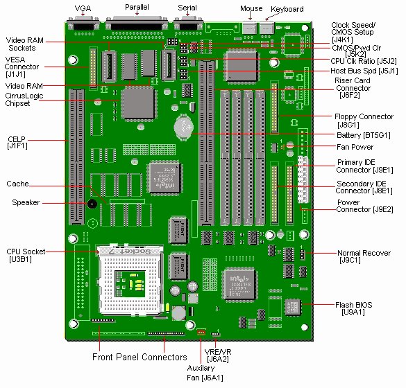
Packard Bell 640 M/Board
The on-board video chip of your computer will automatically be disabled by the installation of a separate video card.
Specification
- Battery : Socketed 3 volt Lithium coin cell battery at location BT5G1.
- BIOS : Flash EEPROM - AMI BIOS
- Bus Architecture : PCI 2.1ISA based system bus.66MHz maximum bus speed
- Cache : 16KB L1 (Internal} write-back Cache (integrated in the CPU).256 KB asynchronous SOJ cache or CELP socket.
- Chipset :
- PC87306VUL Ultra I/O Enhanced Controller.
- PCI064B Super I/0 floppy disk controllers
- Two IMISC471 Clock Chips
- VL82C591PSFC3 PCI to IDE Bridge
- Two VL82C592PSFC2 PCI LB Controllers
- VL82C593PSFC2 PCI/CACHE/MEM Controller
- CPU : Pentium 75 MHz to Pentium 200 MHz.Uses Type 7 CPU Zero Insertion Force (ZIF) CPU Socket.
- Form Factor : LPX.
- Interfaces :
- 1 DB-9 Serial ports for COM1
- 1 DB-25 Parallel port
- 1 PS/2 Keyboard port
- 1 PS/2 Mouse port
- 1 15 pin VGA
- RAM : No onboard memory, 4 SIMM sockets support up to 128 MB of memory.Uses 4/8/16/32 MB 72-pin SIMMs, 60-70ns, EDO, or Fast Page RAM.
- Speaker : On-board piezo speaker.
- UART : Two 16550A compatible chips
- Video : Built-in, Cirrus Logic 5430 or 5440
- Video RAM : Upgradeable to 2 MB.
Jumpers
| Jumper | Description | Setting | Designation |
|---|---|---|---|
| J5J1 | Host Bus Speed | 1-2,4-5 1-2,5-6 2-3,4-5 | 50MHz 60MHz 66MHz |
| J5J2 | CPU Clock Ratio | 1-2,4-5 2-3,4-5 2-3,5-6 1-2,5-6 | x1.5 x2.0 x2.5 x3.0 |
| J4K2 | CMOS Clear | 1-2 2-3 | Normal Clear |
| J4K2 | Password Clear | 4-5 5-6 | Enabled Clear/Disabled |
| J4K1 | ISA Clock Speed Override | 1-2 2-3 | 1/3 PCI Clock 1/4 PCI Clock |
| J4K1 | CMOS Setup Access | 4-5 5-6 | Enabled Access Denied |
| J6A2 | Process Voltage | 1-2 2-3 | Standard Voltage VRE |
| J9C1 | Boot Select | 1-2 2-3 | Normal Recover |
Battery
This 3V Lithium clip in battery is replaceable with a CR2032 battery.
Flash Bios Update
Bios Upgrade Procedure
- Insert the BIOS update diskette into drive A: and reboot the system.
- Press Enter when the first screen appears.
- Select "Update Flash Memory Area from a file" using the Down Arrow key.
- Press Enter.
- The UPDATE FLASH AREA dialog box appears on the screen.
- Select "Update System Bios" and press Enter.
- Select 1006AU0R.BIO file and press Enter.
- Press Enter at the following screen to proceed with programming.
- The BIOS is now re-programmed with the updated BIOS file.
- Remove the disk from drive A.
- Press Enter to reboot the computer system.
- Complete the process by running the CMOS Setup program.
Bios Upgrade Procedure
- Move the 'FLASH NORMAL/FLASH RECOVERY' jumper block,J9C1 from pins 1-2 to pins 2-3.
- Insert the BIOS upgrade diskette and reboot the system. No video is available during the procedure.
- The system beeps once and starts copying the recovery code into the CMOS Flash memory. The system beeps twice as the recovery completes.
- Turn off the system and move the jumper block,J9C1 from pins 2-3 to pins 1-2.
- Leave the BIOS upgrade diskette in the floppy drive, and continue with the original upgrade following the procedure described in 'BIOS UPGRADE PROCEDURE'.
Cache Upgrade
This motherboard may come configured with a CELP socket. This socket supports 256K COAST modules for upgrading the external cache. If there is no CELP socket the motherboard will be configured with 256K cache soldered on board already at locations U2E1, U2E2, U3E1, U3E2, U2D1, U2D2, U3D1, U3D2).
To install cache memory on the motherboard, a 256kB COAST module is required.There are two COAST module configurations supported:
- 1. Modules configured with 32k x 64 asynchronous SRAM with a 5V 8k x 8 Tag SRAM.Eight 32k x 8 3.3V SRAMs are used for the Data RAMs (all are contained on the COAST module).
- 2. Modules configured with 32k x 64 burst or pipelined burst with either four 32k x 16 or two 32k x 32 (no parity) SRAMs (also located on the COAST module).
CPU Upgrades
This motherboard can accommodate the Intel Pentium P75, P90, P100, P120, P133, P150, P166 and P200MHz, and the 150, 166, 180 and 200MHz Intel Pentium Overdrive Processor (MMX).
The upgrade processor installs in the Zero Insertion Force (ZIF) Socket. (U3B1). In the table below you can find the correct jumper settings for each processor:
| CPU Speed | Clock Speed (J5J1) | CPU Multiplier (J5J2) | Host Bus Speed |
|---|---|---|---|
| 75 MHz | 1-2, 4-5 | 1-2, 4-5(x 1.5) | 50 MHz |
| 90 MHz | 1-2, 5-6 | 1-2, 4-5(x 1.5) | 60 MHz |
| 100 MHz | 2-3, 4-5 | 1-2, 4-5(x 1.5) | 66 MHz |
| 120 MHz | 1-2, 5-6 | 2-3, 4-5(x 2.0) | 60 MHz |
| 133 MHz | 2-3, 4-5 | 2-3, 4-5(x 2.0) | 66 MHz |
| 150 MHz | 1-2, 5-6 | 2-3, 5-6(x 2.5) | 60 MHz |
| 166 MHz | 2-3, 4-5 | 2-3, 5-6(x 2.5) | 66 MHz |
| *200 MHz | 2-3, 4-5 | 1-2, 5-6(x 3.0) | 66 MHz |
| **MMX 150 Overdrive | 1-2, 5-6 | 1-2, 4-5 | 60 MHz |
| ** MMX 166 Overdrive | 2-3, 4-5 | 1-2, 4-5 | 66 MHz |
| ** MMX 180 Overdrive | 1-2, 5-6 | 2-3, 5-6 | 60 MHz |
| ** MMX 200 Overdrive | 2-3, 4-5 | 2-3, 5-6 | 66 MHz |
*200 Mhz CPU Upgrade is only possible with Motherboards 181416 or 181426, and Sound Cards other than 030107 or 030101.
** The Pentium Overdrive Processor with MMX technology, is equipped with an on-package voltage regulation, which adapts the 3.3V system voltage to 2.8V processor voltage.
ISA Clock Speed Override (J4K1) should be set to 1-2 for the Pentium 75 and 2-3 for all other processors.
Note - If you wish to install an Intel MMX Overdrive processor, it may be necessary to have BIOS version 1.00.07 CP0R and at least 16MB of RAM installed. The current BIOS version will appear on the screen immediately after switching on the computer.
RAM Upgrades
- If you upgrade the system using EDO DRAM SIMMS, the speed of the SIMMS can be 60 or 70ns.
- If you upgrade the system using Fast Page Mode DRAM SIMMS the speed must be 70ns for ALL Pentium systems.
- The SIMMS are 4/8/16/32MB 72-pin and must be x32 because the motherboard design only supports non parity DRAM.
- Always use silver plated SIMMS (Do not use gold plated SIMMS).
- Upgrade in pairs. This means you have to fill a bank completely. E.g. when up-grading the system with 8MB, you have to use two 4MB SIMMS instead of one 8MB.
- SIMMS in the same bank must be of the same type. Do not mix SIMM types within a bank. It is however possible to use EDO SIMMS in bank 0 and Fast Page Mode in bank 1.
Video Memory Upgrade
You can upgrade the video memory on your system to 2MB by using 256Kx16-70 ns SOJ DRAM chips.You will need two of these chips to perform the upgrade.