Acer File Extensions |
Packard Bell Phoenix M/Board
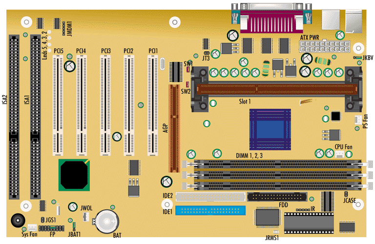
Specification
- Bus : 133 MHz front side bus is supported
- Cache : Integrated on the SEC cartridge
- Chipset : VIA Apollo Pro133
- CPU Support : SEC1 or SEC2 cartridge, placed in Slot 1
- Expansion Slots : Four 32-bit Master PCI Bus slots, one ISA slot, one shared PCI/ISA slot
- Form Factor : ATX
- RAM : Three 168-pin DIMM sockets supporting up to 1.5 GB of SDRAM memory
- Video : None
Upgrades
- CPU : CPU upgradable using Pentium III up to 800/100 MHz and 800/133 MHz, Pentium II up to 450/100 and Celeron up to 433/66.
- RAM : RAM upgradable up to 1.5 GB using 3.3 V gold-plated SDRAM DIMMs. The Phoenix motherboard only accepts 168-pin DIMM modules. Only gold-plated DIMMs may be used, as the sockets on the motherboard are also gold-plated, and oxidation must be prevented. Only use unbuffered 3.3 V SDRAM. Single- or double-sided DIMMs may be used. SDRAM DIMMs may be up to 512 MB big. Memory size and speed can vary between sockets. Parity (×72) DIMMs can be installed, ECC memory checking is supported.
Diagnostic LEDs
| Display (LED 2-3-4-5) | BIOS operation |
|---|---|
| Red - Red - Red - Red | Power on, starting BIOS |
| Red - Red - Red - Green | Early chipset initialisation |
| Red - Red - Green - Red | Memory detection test. |
| Red - Red - Green - Green | Decompressing BIOS image to RAM for fast booting |
| Red - Green - Red - Red | Initialising keyboard controller |
| Red - Green - Red - Green | Test shadow RAM |
| Red - Green - Green - Red | Processor initialisation |
| Red - Green - Green - Green | Testing RTC |
| Green- Red - Red - Red | Initialising video interface |
| Green - Red - Red - Green | BIOS sign on |
| Green - Red - Green - Red | Testing base and extended memory |
| Green - Red - Green - Green | Assign resource to all ISA |
| Green - Green - Red - Red | Initialising hard drive controller |
| Green - Green - Red - Green | Initialising floppy drive controller |
| Green - Green - Green - Red | Assign IRQs to PCI devices |
| Green - Green - Green - Green | Booting operating system |
Jumpers
| Jumper | Configuration |
|---|---|
| JP6 - Clear BIOS Settings | 1-2 : Normal operation (default) 2-3 : Clear current BIOS settings |
| SW1 & SW2 - Set Bus Speed | Closed, Closed : Auto Open, Closed : 100MHz Open, Open : 133MHz |
| JP11 - Set Keyboard Wakeup | 1-2: Enable Keyboard WakeUp (default) 2-3: Disable Keyboard WakeUp |